Projects
Personal, Academic, and Professional Projects
ME 72 Senior Design Capstone (September 2024 - March 2025)
Robot Hockey Competition (in progress)
- This course is a group project spanning two terms. It fulfills the Mechanical Engineering thesis/capstone requirement at Caltech. I am my team's software/electronics lead and a key contributor to mechanical design and fabrication.
- The project is modeled after industry, requiring strict budget management with usage of Bills of Materials (BOMs), a PDR and CDR, demonstration timelines, and strict keeping of an engineering notebook.
Work Done
- As software and electronics lead, I solely wrote the driving code and remote control interface for the robot. I also selected, designed, and assembled all of the mechatronics in the robot. The code for this robot can be found on my github.
- All of my idea generation and personal work can be found in my design notebook.
- A summarized conclusion of our work as a team with visuals can be found in our final report.
Lessons Learned and Challenges Overcome
One challenge my team encountered during the mobility demo was difficulty handling the puck as well as making precise turns. I resolved this issue by turning our single stick arcade drive into double stick arcade drive. I also programmed a three-stage gearing system that allows low, medium, and high speed/torque. The highest setting is for direct bot on bot contact and for traversing the field quickly. The lowest setting is for precise turns and puck maneuvers. The medium setting is great for balanced driving while still duty-cycling to maintain battery life.
Further lessons came during mechanical fabrication. I was in charge of pinning our gears to the shafts of our transmission via the mill. When attempting to use the gear's set screw to hold it in place for pinning, the screw ate through the brass gear. I rapidly redrilled and retapped another hole on the other side of the gear so the set screw could be put in place.
During this process, I was concerned about the double shear the pins would be under. I had done detailed and robust calculations, but still worried the pins available would be too thin to stand up to our robot's maximum torque. I received great advice from my Professor Dr. Michael Mello. He encouraged me to not hold up the entire project. I had done the work, now it was time to experiment and prototype. I wouldn't hold up a project deadline in industry by a week to just run more calculations, so I shouldn't do it here either.
These and more were some of the many industry-related challenges overcome and lessons learned during the first half of this project.
Second SURF Project (June-August 2024)
Training a Biped to Walk with Behavior Cloning and Reinforcement Learning
With Caltech's Autonomous Robotics and Controls Lab (ARCL) led by Professor Soon-Jo Chung
- The goal of this project was to better understand how to use machine learning to control a bipedal robot's walking behavior in a novel direction.
- The novel direction chosen was to use behavior cloning on a a capture-point inverse kinematics system and inverse dynamics system.
- The end goal is to have successful tests in simulation before transferring the model to hardware
Concepts Used
The concepts primarily used in this project were types of Machine Learning (ML). I used Conservative Q-Learning (CQL), a form of Offline Reinforcement Learning (RL), and Behavior Cloning (BC) to attempt to create a bipedal walking algorithm for the robot.
Work Done
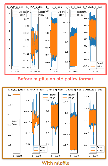
The simulation would run a little slow using the simple BC policy format, so I used a different policy saving format known as an "mlpfile" which both improved simulation speed and model performance.
Improved Model Performance Via Mlpfile
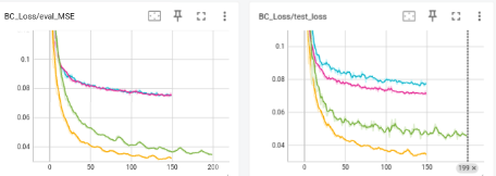
Improving Training Performance Via TensorBoard
Additional Work Done and Takeaways
Further work included improving post-simulation data visualization, fixing the broken model training pipeline, collecting robust training data, reviewing and implementing CQL, and tuning/improving model parameters. More details on the work completed can be found in the final presentation, first and second interim reports, and the final report.
Having no prior ML experience, this project helped me learn a lot about the world of Machine Learning in robotics, and I now have the tools and knowledge to apply neural networks to any future work in robotics.
ME/CS/EE 169 Final Project (April - June 2024)
Designing a Fully Autonomous Miniature Car
Completed Hardware
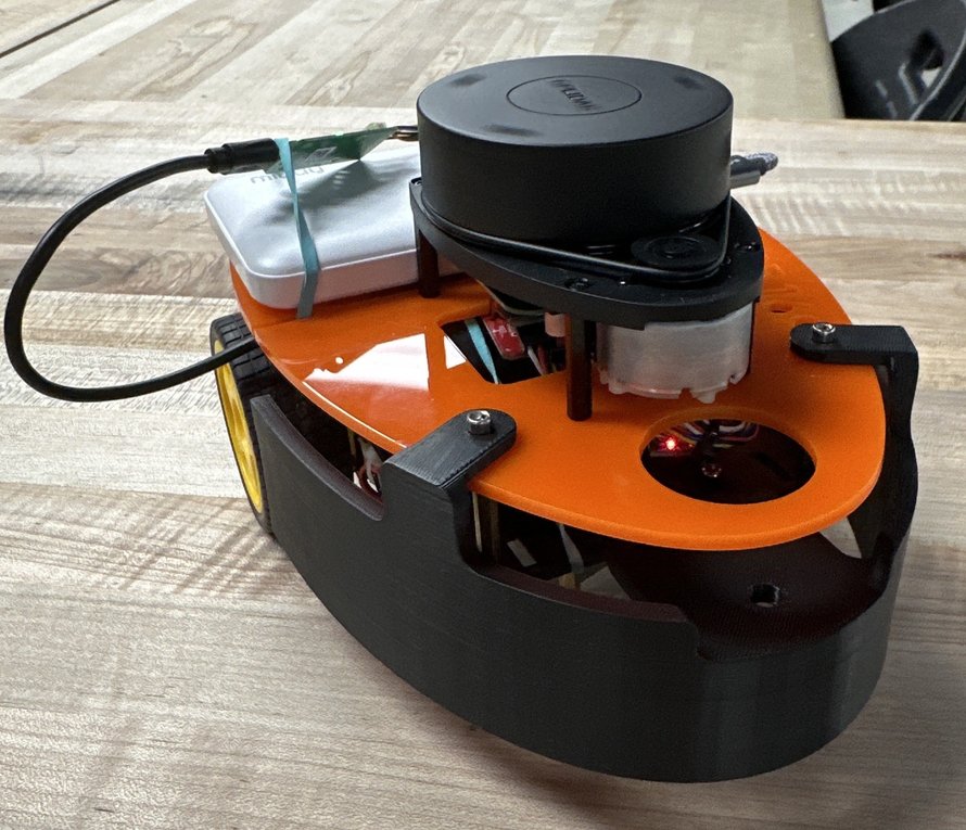
The completed robot hardware consists of the following (assembled from scratch):
- Two motor encoders
- A small motor driver
- A Raspberry Pi (Generation 4)
- A LiDAR Sensor (attached via PCB)
- An IMU (with an accelerometer and gyroscope)
- Two external rechargeable battery packs
- Two actuated wheels and a third passive wheel
- 3D printed platforms, mounts, and guards
- A front mounted camera for detecting Aruco markers
Software Architecture
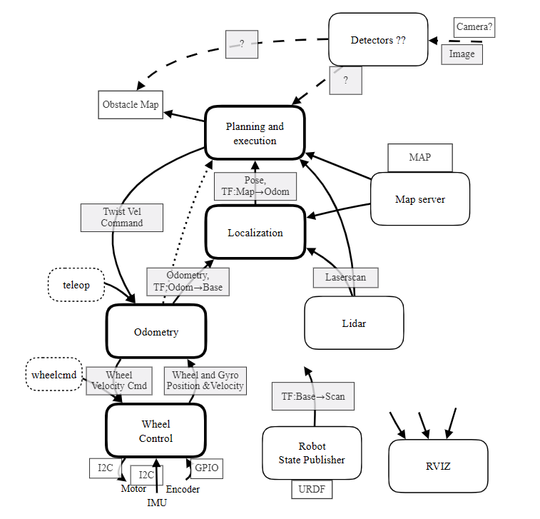
The code is fundamentally organized in three layers. The "lowest" layer handles direct interfacing with the drivetrain. This includes velocity control, odometry, and encoder commands. The middle level finishes the odometry, incorporates the gyroscope, and sets up the autonomous driving algorithm. This highest level includes the planning algorithm (A*/PRM was the planner of choice), the localization algorithm, and utility files for the planner. The main framework for all of this was ROS2 Humble, and RVIZ was used to visualize the robot and the planner, shown below.
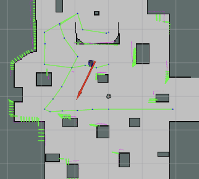
The purple lines indicate measured LiDAR points, the blue dots are the planning points, and the green lines connect the path chosen. Green rectangles help point the measured walls to the believed walls, allowing for localization. This map is known, but on an unknown map (which the robot can also navigate), the only details would be the outer walls.
Final Performance Demonstration
Project Takeaways
It was one of two projects I've done where the robot was essentially put together from the ground up, I was able to implement and expand on the planning knowledge from my previous courses, while gaining a greater understanding for all of the code management needed to design a robot from scratch. The robot performed well in the final assessment on both the known and unknown maps.
Some of the biggest challenges overcame included tuning the localization parameters (the believed and actual maps would often be a little off, meaning the driving algorithm was made to be more robust). Another solution was running the planning algorithm again if the robot was stuck for a certain period of time. Additionally, the driving algorithm was coded to have emergency evasive measures for if the robot was stuck in a corner. Another problem was that the robot's driving would often leave it off course, so a smoother spline-based driving algorithm was included, with the driving speed also being a spline so as to only move at top speed when at the midpoint between two waypoints.
ME/EE/CS 134 Final Project (January - March 2024)
Designing a 7-DOF Arm for a Complex Task with Recovery Modes
This project was a four person team assignment with two Computer Science majors, an Electrical Engineering major, and me. The hardware, game materials, and code were all built from ground zero.
As the only mechanical engineer, my focus was primarily the fabrication of game materials and the robot hardware design. However, I worked on all parts of the code and in particular helped design the game playing algorithm and recovery modes demonstrated in the video.
Final Design of Arm with Game Board (No End-Effector)
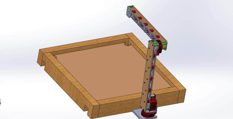
Torque calculations and light testing would indicate that the arm was slightly too heavy to reach the far edge of the board without exceeding the torque limit on the tilting elbow motor. So, only the aluminum piece was kept on the forearm.
Final Demonstration
The final result was a robot arm that could play Carrom completely autonomously. This included a simple machine learning algorithm via OpenCV that allowed the robot to detect a signal for when its turn has begun. Additionally, the robot is robust against suboptimal playing states, poor game setup, and even cheaters. More information about the robot's functionalities and the work done can be found in the final report and presentation.
Challenges Overcome
One of the challenges I personally faced was in the design of the arms. Originally utilizing a flat aluminum design, when testing the robot, it became apparent that some wiggle would happen as the arm moved around. This is because due to the flat design, the robot arms were more subject to weak axis and neutral axis or torsional bending. I was taking a class on this concurrently (ME 50a), so after learning a little more about this (I identified that it was the second and fourth bending modes giving us the most trouble), I corrected the design.
Another challenge encountered was in the board fabrication. Most of the budget was spent on other things for the robot, so I had to be resourceful when making the game board. I was able to find scrap 2x4s and buy small L-braces for supporting the board from underneath. We wanted the robot to be able to detect the pucks after they've been scored, so I cut holes in each corner of the frame and placed ramps under the board holes through the frame holes so that the pucks could slide back out into the robot's vision. I made the board itself out of acrylic so that I could cut the corner holes easily and sand down the edges, ensuring it was as flat as possible for gameplay.
One last challenge I'll mention is the navigation of the recovery modes. Having the robot be able to detect when other pucks are near the striker and not interfere with them was difficult. The detector needed to be quite robust (contours would often overlap with the striker and confuse the robot). Additionally, the robot hand placement needed to be precise and robust against differences in board elevation. We also found that an arbitrary hand position would sometimes result in the solenoid hitting a wall. So, we implemented a universal wall detector that would be factored in with other pucks in the area to create an optimized wrist rotation algorithm. Note that the wall detector takes priority over the nearby puck detector ensuring the solenoid will never be hit while still getting the best possible angle to avoid touching non-striker pucks.
ME/CS/EE 133b Final Project (February - March 2024)
Solving Locked Door Mazes with EST and RRT
This was a shorter (about three weeks long) project at the end of my robotic planning class. I worked in a trio to come up with original ways to use different planning algorithms test our hypotheses.
Video and Demonstration
Further Information
More information about the specifics of the project can be found in the final report.
Some conclusions and takeaways include the fact that the RRT 90 ended up performing better than an EST, which was surprising for me, personally. It was certainly expected that the plain RRT would perform poorly in such an enclosed space. The EST 90 only being marginally better was also interesting, as while a true 90 degree EST must certainly excel in an enclosed space defined by 90 degree turns? When researching a 90 degree EST, I could barely find anything, and I essentially designed this algorithm from scratch.
The hardest challenges involved sampling and growing the tree. When making the RRT 90 algorithm, I initially noticed it would often go back and forth in one small area, so we changed the growing algorithm to block it from growing in the same direction it just came. Another issue was the fact that the tree would cluster lots of nodes around locked doors before grabbing the key needed for the door. We changed the tree behavior to stop it from doing this so much and had a modified algorithm that included more spread out sampling. Overall, the node restriction and the unpredictable behavior of unlocking different doors proved a difficult challenge that we managed to overcome.
ME/CS/EE 133a Final Project (November - December 2023)
SPOT Catching a Ball from a Planted Stance
This was another shorter project that looked to apply fundamental robotic kinematics and ROS2 knowledge in a creative direction using a known pre-made robot model.
Video Demonstration
Further Information
This was a relatively simple and lighthearted project meant to showcase our skills in the fundamental aspects of robotics. More information about the project can be found in the final report.
Beyond learning and applying robotics fundamentals, there were plenty of challenges to overcome. The hardest part of the project was easily ensuring the feet stay in place while the body moves around and the legs reach for the ball. Since the base/body is considered the end of a kinematic chain, we had to coordinate two separate kinematic chains (arms and legs) while ensuring the feet stay still. Another challenge was keeping track of the ball position and velocity relative to the frame of both the hand, the body, and the legs/feet since each had its own position and velocity relative to the ball. Applying our understanding of transformation matrices and reference frames allowed us to put everything together and get SPOT catching the ball!
First SURF Project (June - August 2023)
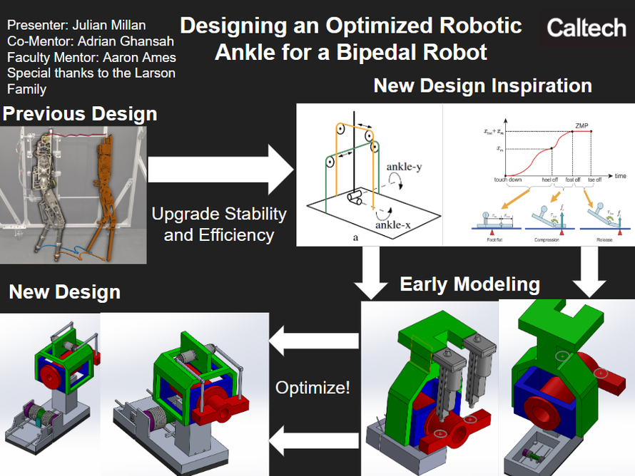
Designing an Optimized Robotic Ankle for a Bipedal Robot
With Caltech's AMBER Lab led by Professor Aaron Ames
My first experience in research had the task of designing an actuated ankle for a bipedal robot with a passive toe joint.
Presentation Poster
Further Information
Details about the work done and the project itself can be found in the first and second interim reports as well as the final report.
I gained a lot of valuable experience in understanding robotic hardware and how to apply my mechanical knowledge in a robotics sense. One of the challenges I overcame was how, after completing my first design, I had found it was much too big and heavy. The size of the bipedal robot is a good bit smaller than the typical human. Additionally, the materials I was using were too heavy and expensive. To make matters worse, when I shrunk down the design and made it lighter, I realized that the linear actuators I had originally planned to use were now too big for the ankle. I solved these issues by opting for cutouts in the material, shrinking things down, and using rotary motors to control the ankle instead. I learned a valuable lesson in the intersection between design and real life constraints, and how important it is to understand the greater whole of the project if you're designing a smaller piece of it.
ME 14 Final Project (April - June 2023)
A Can-Crushing Replica of Wall-E
A several-week project with a team of five that focused on applying mechanical design and mechatronic skills. I was in charge of the electronics/mechatronics as well as designed much of the body. More about the work I did can be read in my submitted contribution statement.
Video Demonstration
Further Information
Taking on the task of electronic design, programming, and a large part of the mechanical design was certainly no easy feat. One of the biggest hardships we faced was when our initial design broke under the force of the crushing motor, essentially ripping the robot frame apart. We needed a stronger method to keep the walls together because the acrylic glue we had been using wasn't strong enough to hold up when the can would get crushed against the back wall. I came up with the idea to use L-Brackets around the entire frame, with the strongest and heaviest supporting the back wall. This proved to be a strong solution.
Another challenge encountered happened when the rack and pinion system ran into the back wall, causing kickback on the gear motor and breaking its mount. We redesigned a heavier and stronger mount. I also changed the motor code and how it bound to the remote controller we were using to be easier to control and have a slower rotation speed.
One of the more important habits/takeaways I had was the keeping of a design notebook. Keeping a log of all my activities and drawings helped when it came time to do the final report and is a habit I've kept through my two SURF projects as well. This was my first major mechanical design project and while wrought with difficulties, I learned a lot of fundamentals that I would use.